
Analyze how the vfd convert frequency
2024-07-02
01 Variable frequency drive element - rectifier
Due to the difficulty in changing the frequency of the AC sine wave in communication mode, the first task of the frequency converter is to convert the waveform into DC. To make it look like AC, operating DC is relatively easy. The first component of all frequency converters is a device called a rectifier or converter, as shown in the following figure:
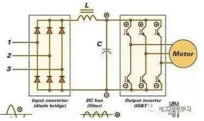
The rectifier circuit converts alternating current into direct current, and its operation is roughly the same as that of a battery charger or arc welding machine. It uses a diode bridge to limit the movement of AC sine waves in only one direction. The result is that the fully rectified AC waveform is interpreted by the DC circuit as a local DC waveform. The three-phase inverter receives three independent AC input phases and converts them into a single DC output.
Most three-phase frequency converters can also accept single-phase (230V or 460V) power supply, but due to only two input branches, the output (HP) of the frequency converter must be derated because the generated DC current is proportionally reduced. On the other hand, true single-phase frequency converters (single-phase frequency converters that control single-phase motors) utilize single-phase input and generate DC output proportional to the input.
There are two reasons why three-phase motors are more commonly used than single-phase counter components when it comes to variable speed operation. Firstly, they have a wider power range. On the other hand, single-phase motors typically require some external intervention to start rotating.
02 Frequency converter components - DC bus
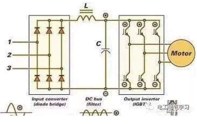
The second component of the DC bus (shown in the figure) is not visible in all frequency converters because it does not directly affect the operation of the frequency converter. However, it always exists in high-quality universal frequency converters. The DC bus uses capacitors and inductors to filter out the AC ripple voltage in the converted DC power, and then enters the inverter section. It also includes filters that prevent harmonic distortion and can provide feedback to the inverter power supply. Older frequency converters require separate line filters to complete this process.
03 Variable frequency drive components - inverter
On the right side of the illustration is the "viscera" of the frequency converter (as shown by the inverter in the figure). The inverter uses three sets of high-speed switching transistors (IGBT shown in the figure) to create DC "pulses" of all three phases simulating AC sine waves. These pulses not only determine the voltage of the wave, but also its frequency. The term inverter or inverter means "reverse", simply put, the up and down movement of the generated waveform. Modern frequency converters and inverters use a technology called Pulse Width Modulation (PWM) to regulate voltage and frequency.
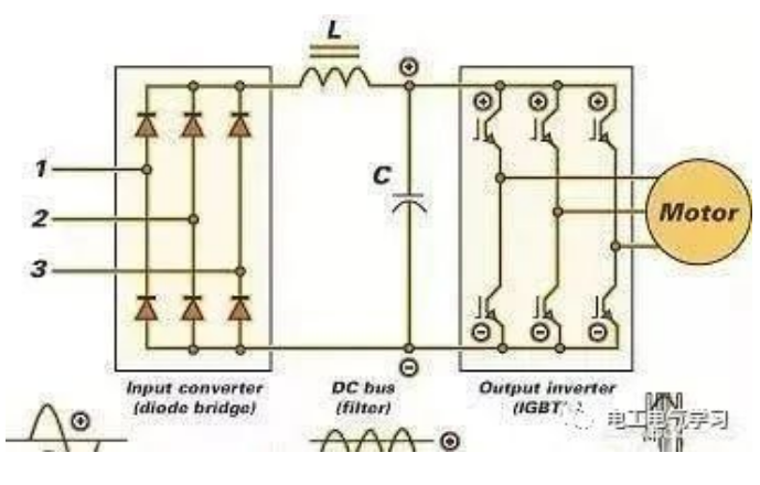
Then let's talk about IGBT, which refers to an insulated gate bipolar transistor, which is a switching (or pulse) component of an inverter. Transistors (replacing vacuum tubes) play two roles in our electronic world. It can act as an amplifier and increase the signal, or as a switch, simply turning on and off the signal. IGBT is a modern version that can provide higher switching speeds (3000-16000 Hz) and reduce heat generation. A higher switching speed can improve the accuracy of AC wave simulation and reduce motor noise. The decrease in heat generated means that the heat sink is smaller, so the frequency converter occupies a smaller area.
04 Inverter PWM waveform
The following figure shows the waveform generated by the PWM inverter compared to the real AC sine wave. The inverter output consists of a series of rectangular pulses with fixed height and adjustable width. In this special case, there are three sets of pulses - a wide set in the middle, and a narrow set at the beginning and end of the positive and negative parts of the AC cycle.

The sum of the areas of the pulses is equal to the effective voltage of the true AC wave. If you want to cut off the pulse portion above (or below) the actual communication waveform and fill the blank area below the curve with them, you will find that they match almost perfectly. It is precisely in this way that the frequency converter can control the voltage of the motor.
The sum of the pulse width and the blank width between them determines the frequency of the waveform seen by the motor (hence PWM or pulse width modulation). If the pulse is continuous (i.e. there is no blank), the frequency is still correct, but the voltage will be much larger than a true AC sine wave. According to the required voltage and frequency, the frequency converter will change the height and width of the pulse, as well as the blank width between the two.
Some people may want to know how this "fake" AC (actually DC) operates an AC induction motor. After all, does it require an alternating current to "induce" the current and corresponding magnetic field in the motor rotor? So, AC will naturally cause induction because it is a constantly changing direction. On the other hand, DC will not act normally once the circuit is activated.
However, if the DC is turned on and off, it can sense current. For those who are old, the car ignition system (before solid-state ignition) once had a set of points in the distributor. The purpose of these points is to pulse from the battery to the coil (transformer). This induces an electric charge in the coil and then raises the voltage to a level that allows the spark plug to ignite. The wide DC pulse seen in the above figure is actually composed of hundreds of individual pulses, and the opening and closing motion output by the inverter allows for DC induction to occur.
The sum of the pulse width and the blank width between them determines the frequency of the waveform seen by the motor (hence PWM or pulse width modulation). If the pulse is continuous (i.e. there is no blank), the frequency is still correct, but the voltage will be much larger than a true AC sine wave. According to the required voltage and frequency, the frequency converter will change the height and width of the pulse, as well as the blank width between the two.
Some people may want to know how this "fake" AC (actually DC) operates an AC induction motor. After all, does it require an alternating current to "induce" the current and corresponding magnetic field in the motor rotor? So, AC will naturally cause induction because it is a constantly changing direction. On the other hand, DC will not act normally once the circuit is activated.
However, if the DC is turned on and off, it can sense current. For those who are old, the car ignition system (before solid-state ignition) once had a set of points in the distributor. The purpose of these points is to pulse from the battery to the coil (transformer). This induces an electric charge in the coil and then raises the voltage to a level that allows the spark plug to ignite. The wide DC pulse seen in the above figure is actually composed of hundreds of individual pulses, and the opening and closing motion output by the inverter allows for DC induction to occur.
05 effective voltage
One factor that complicates AC power is that it constantly changes the voltage, from zero to a certain maximum positive voltage, then back to zero, then to some maximum negative voltage, and then back to zero. How to determine the actual voltage applied to the circuit? The illustration below shows a 60Hz, 120V sine wave. However, it should be noted that its peak voltage is 170V. If its actual voltage is 170V, how can we call it a 120V wave?
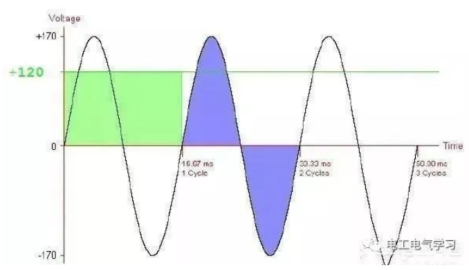
In a cycle, it starts from 0V, rises to 170V, and then drops again to 0. It continues to drop to -170, and then rises again to 0. The area of the green rectangle with the original upper boundary at 120V is equal to the total area of the positive and negative parts of the curve. Is 120V the average level?
Okay, if we were to average all voltage values at each point throughout the entire cycle, the result would be approximately 108V, so it cannot be the answer. So why is this value measured by VOM as 120V? It is related to what we call the effective voltage.
If you want to measure the heat generated by the direct current flowing through a resistor, you will find that it is greater than the heat generated by the equivalent alternating current. This is because AC does not maintain a constant value throughout the entire cycle. If conducted under controlled conditions in the laboratory, it is found that a specific DC current generates a 100 degree heat increase, and its AC equivalent will produce a 70.7 degree increase or a 70.7% DC value. So the effective value of AC is 70.7% of DC. It can also be seen that the effective value of the AC voltage is equal to the square root of the sum of the squared voltages in the first half of the curve.
If the peak voltage is 1 and various voltages from 0 degrees to 180 degrees are to be measured, the effective voltage will be a peak voltage of 0-707. 0.707 times the peak voltage of 170 in the figure is equal to 120V. This effective voltage is also known as root mean square or RMS voltage. Therefore, the peak voltage is always 1.414 of the effective voltage. 230V AC current has a peak voltage of 325V, while 460 has a peak voltage of 650V.
In addition to frequency changes, even if the voltage is independent of the operating speed of the AC motor, the frequency converter must also change the voltage.
The figure shows two 460V AC sine waves. Red represents the 60Hz curve, while blue represents the 50Hz curve. Both have a peak voltage of 650V, but 50Hz is much wider. You can easily see that the area within the first half of the 50Hz curve (0-10ms) is larger than the first half of the 60Hz curve (0-8.3ms). Moreover, as the area under the curve is directly proportional to the effective voltage, its effective voltage is higher. As the frequency decreases, the increase in effective voltage becomes more severe.
Okay, if we were to average all voltage values at each point throughout the entire cycle, the result would be approximately 108V, so it cannot be the answer. So why is this value measured by VOM as 120V? It is related to what we call the effective voltage.
If you want to measure the heat generated by the direct current flowing through a resistor, you will find that it is greater than the heat generated by the equivalent alternating current. This is because AC does not maintain a constant value throughout the entire cycle. If conducted under controlled conditions in the laboratory, it is found that a specific DC current generates a 100 degree heat increase, and its AC equivalent will produce a 70.7 degree increase or a 70.7% DC value. So the effective value of AC is 70.7% of DC. It can also be seen that the effective value of the AC voltage is equal to the square root of the sum of the squared voltages in the first half of the curve.
If the peak voltage is 1 and various voltages from 0 degrees to 180 degrees are to be measured, the effective voltage will be a peak voltage of 0-707. 0.707 times the peak voltage of 170 in the figure is equal to 120V. This effective voltage is also known as root mean square or RMS voltage. Therefore, the peak voltage is always 1.414 of the effective voltage. 230V AC current has a peak voltage of 325V, while 460 has a peak voltage of 650V.
In addition to frequency changes, even if the voltage is independent of the operating speed of the AC motor, the frequency converter must also change the voltage.
The figure shows two 460V AC sine waves. Red represents the 60Hz curve, while blue represents the 50Hz curve. Both have a peak voltage of 650V, but 50Hz is much wider. You can easily see that the area within the first half of the 50Hz curve (0-10ms) is larger than the first half of the 60Hz curve (0-8.3ms). Moreover, as the area under the curve is directly proportional to the effective voltage, its effective voltage is higher. As the frequency decreases, the increase in effective voltage becomes more severe.

If a 460V motor is allowed to operate at these higher voltages, its lifespan can be greatly reduced. Therefore, the frequency converter must continuously change the "peak" voltage relative to frequency to maintain a constant effective voltage. The lower the operating frequency, the lower the peak voltage, and vice versa.
You should now have a good understanding of the working principle of frequency converters and how to control motor speed. Most frequency converters allow users to manually set the motor speed through multi position switches or keyboards, or use sensors (pressure, flow, temperature, liquid level, etc.) to automate the process.
You should now have a good understanding of the working principle of frequency converters and how to control motor speed. Most frequency converters allow users to manually set the motor speed through multi position switches or keyboards, or use sensors (pressure, flow, temperature, liquid level, etc.) to automate the process.
13 commonly used parameters of frequency converters
What is the V/F control
Related Article
There are many parameters to set for the frequency converter, and each parameter has a certain selection range. During use, it is often encountered that the frequency converter cannot work properly due to improper setting of individual parameters. Therefore, it is necessary to set the relevant parameters correctly.
13 commonly used parameters of frequency converters
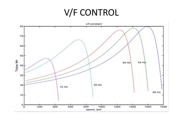
V/F control is a technology used to regulate the speed of AC motors, also known as voltage frequency control. In V/F control, the speed and torque of the motor are controlled by adjusting its voltage and frequency. This control method is widely used in various industrial applications, such as fans, pumps, compressors, etc.
What is the V/F control