
13 commonly used parameters of frequency converters
2024-07-02
01 Control mode
Namely, speed control, torque control, PID control, or other methods. After adopting control methods, it is generally necessary to perform static or dynamic identification based on control accuracy.
02 Minimum operating frequency
The minimum speed at which the motor operates. When the motor operates at low speeds, its heat dissipation performance is poor. Prolonged operation at low speeds can cause the motor to burn out. Moreover, at low speeds, the current in the cable also increases, which can cause the cable to heat up.
03 Maximum operating frequency
The maximum frequency of a typical frequency converter can reach 60Hz, and some even reach 400Hz. High frequencies will cause the motor to operate at high speed. For ordinary motors, their bearings cannot operate at the rated speed for a long time. Can the rotor of the motor withstand such centrifugal force.
04 Carrier frequency
The higher the carrier frequency is set, the larger the higher the harmonic component, which is closely related to factors such as cable length, motor heating, cable heating, and frequency converter heating.
05 Motor parameters
The frequency converter sets the power, current, voltage, speed, and maximum frequency of the motor in the parameters, which can be directly obtained from the motor nameplate.
06 frequency hopping
At a certain frequency point, resonance may occur, especially when the entire device is relatively high; When controlling the compressor, avoid the vibration point of the compressor.
07 Acceleration and deceleration time
Acceleration time refers to the time required to increase the output frequency from 0 to the maximum frequency, while deceleration time refers to the time required to decrease from the maximum frequency to 0. Usually, the frequency setting signal is used to determine the acceleration and deceleration time. When accelerating the motor, it is necessary to limit the rate of increase set by the frequency to prevent overcurrent, and when decelerating, limit the rate of decrease to prevent overvoltage.
Acceleration time setting requirement: Limit the acceleration current to below the overcurrent capacity of the frequency converter, so as not to cause the frequency converter to trip due to overcurrent stall; The key to setting the deceleration time is to prevent excessive voltage in the smoothing circuit from causing the regeneration overvoltage to stall and trip the frequency converter. The acceleration and deceleration time can be calculated based on the load, but in debugging, it is often adopted to set a longer acceleration and deceleration time based on the load and experience, and observe whether there are overcurrent and overvoltage alarms by starting and stopping the motor; Then gradually shorten the set time for acceleration and deceleration, with the principle of no alarm during operation. Repeat the operation several times to determine the optimal acceleration and deceleration time.
08 Torque increase
Also known as torque compensation, it is a method of increasing the low frequency range f/V to compensate for the torque reduction caused by the resistance of the stator winding of the motor at low speeds. When set to automatic, the voltage during acceleration can be automatically increased to compensate for the starting torque and ensure smooth acceleration of the motor. If manual compensation is used, the optimal curve can be selected through experiments based on the load characteristics, especially the starting characteristics of the load. For variable torque loads, improper selection can result in excessively high output voltage at low speeds, wasting electrical energy, and even causing high current when starting the motor with load but unable to increase speed.
09 Electronic thermal overload protection
This function is set to protect the motor from overheating. It is used by the CPU in the frequency converter to calculate the temperature rise of the motor based on the operating current value and frequency, thereby providing overheating protection. This function is only applicable to "one to one" situations, and in "one to many" situations, thermal relays should be installed on each motor.
Electronic thermal protection setting value (%)=[rated current of motor (A)/rated output current of frequency converter (A)] x 100%.
Electronic thermal protection setting value (%)=[rated current of motor (A)/rated output current of frequency converter (A)] x 100%.
10 Frequency limitation
The upper and lower limit amplitudes of the output frequency of the frequency converter. Frequency limitation is a protective function designed to prevent accidental operation or failure of external frequency setting signal sources, which may cause the output frequency to be too high or too low, in order to prevent damage to the equipment. Set according to the actual situation in the application. This function can also be used for speed limiting. For some belt conveyors, due to the limited amount of conveyed materials, in order to reduce mechanical and belt wear, a frequency converter can be used for driving, and the upper frequency limit of the frequency converter can be set to a certain frequency value, so that the belt conveyor can operate at a fixed and lower working speed.
11 bias frequency
Some are also called deviation frequency or frequency deviation setting. Its purpose is to adjust the output frequency when the frequency is set by an external analog signal (voltage or current), using this function to adjust the output frequency when the frequency setting signal is at its lowest. When the frequency setting signal of some frequency converters is 0%, the deviation value can act within the range of 0 to fmax. Some frequency converters (such as Mingdian She and Sanken) can also set the bias polarity. If in debugging, when the frequency setting signal is 0%, the output frequency of the frequency converter is not 0Hz, but xHz, then setting the bias frequency to negative xHz can make the output frequency of the frequency converter 0Hz.
12 Frequency setting signal gain
This function is only effective when setting the frequency using external analog signals. It is used to compensate for the inconsistency between the external set signal voltage and the internal voltage of the frequency converter (+10v); At the same time, it is convenient to simulate the selection of signal voltage. When the analog input signal is at its maximum (such as 10V, 5V, or 20mA), calculate the frequency percentage that can output the f/V graph and set it as a parameter; If the external signal is set to 0-5V, and the output frequency of the frequency converter is 0-50Hz, set the gain signal to 200%.
13 Torque limitation
It can be divided into two types: driving torque limit and braking torque limit. It is based on the output voltage and current values of the frequency converter, and torque calculation is performed by the CPU. It can significantly improve the impact load recovery characteristics during acceleration, deceleration, and constant speed operation. The torque limiting function can achieve automatic acceleration and deceleration control. Assuming that the acceleration and deceleration time is less than the load inertia time, it can also ensure that the motor automatically accelerates and decelerates according to the torque setting value.
The drive torque function provides powerful starting torque. During steady-state operation, the torque function controls the motor slip and limits the motor torque to the maximum set value. When the load torque suddenly increases, even when the acceleration time is set too short, it will not cause the frequency converter to trip. When the acceleration time is set too short, the motor torque will not exceed the maximum set value. A high driving torque is beneficial for starting, so setting it at 80-100% is more appropriate.
The smaller the set value of the braking torque, the greater the braking force, making it suitable for situations with rapid acceleration and deceleration. If the set value of the braking torque is too small, overvoltage alarms may occur. If the braking torque is set to 0%, the total amount of regeneration added to the main capacitor can be close to 0, so that the motor can decelerate to a stop without tripping when decelerating without using the braking resistor. But on some loads, such as when the braking torque is set to 0%, there may be a brief idle phenomenon during deceleration, causing the frequency converter to start repeatedly and the current to fluctuate significantly. In severe cases, it may cause the frequency converter to trip, and attention should be paid.
Analyze how the vfd convert frequency
Related Article
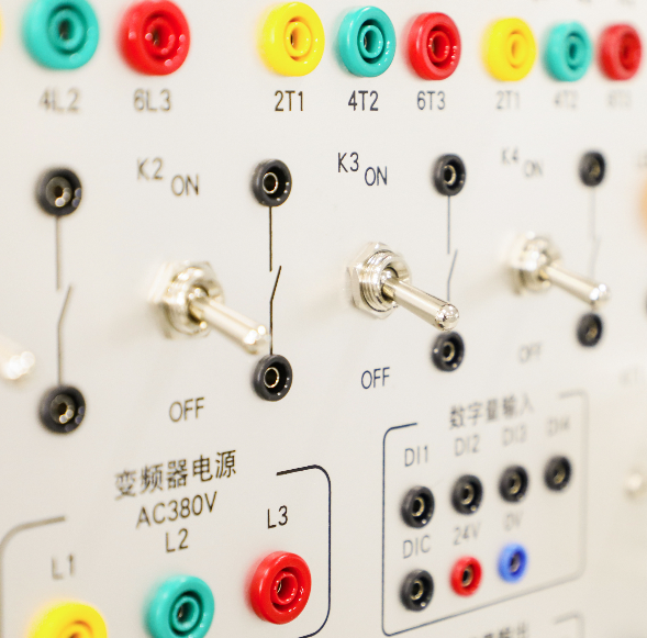
Since the emergence of automatic induction motors, variable frequency operation has existed in the form of AC generators. Change the speed of the generator and its output frequency. Before the emergence of high-speed transistors, this was one of the main ways to change the motor speed, but the frequency change was limited due to the generator speed reducing the output frequency instead of voltage.
Analyze how the vfd convert frequency
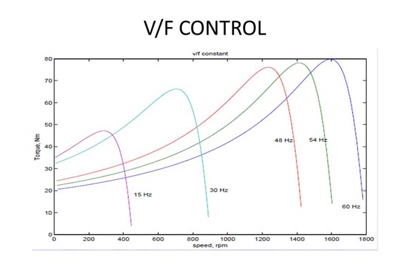
V/F control is a technology used to regulate the speed of AC motors, also known as voltage frequency control. In V/F control, the speed and torque of the motor are controlled by adjusting its voltage and frequency. This control method is widely used in various industrial applications, such as fans, pumps, compressors, etc.
What is the V/F control